PLYWOOD INCLINED BEAM CAPACITY CHECK
BS 5268-2:2002
1.0 INPUT DATA
1.1 Geometrical Properties
Span (horizontal projection) Lhorizontal = mm
Plywood Thickness h = mm
Plywood Width b = mm
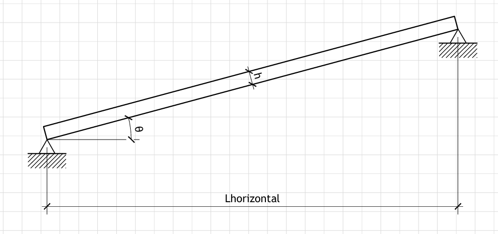
Angle of inclination θ = deg
Figure 1: Geometry
Plywood inclined at angle θ with horizontal span L_horizontal
Effective Span along the inclined length Leff,inclined =
Lhorizontal/cos(θ)
Leff,inclined = 380/cos(54°) = 646.15 mm
1.2 Loading
Uniformly Distributed Load (UDL) qLL = kPa
Total UDL on specified width wvert =
qLL×b/1000
wvert = 2×1000/1000 = 2.00 kN/mm
Concentrated Load (mid-span) PL,LL = kN
1.3 Material Properties (BS 5268-2:2002)
Characteristic Bending Stress fm,g = N/mm²
Characteristic Shear Stress fv,g = N/mm²
Characteristic Compression Stress fc,g = N/mm²
Mean Modulus of Elasticity Emean = N/mm²
Minimum Modulus of Elasticity Emin = N/mm²
1.4 Modification Factors
Load Duration Factor K3 =
Depth Factor K7 =
Load Sharing Factor K8 =
Compression Factor K22 =
2.0 CALCULATIONS
2.1 Section Properties
Section Area A = b×h
A = 1000×12 = 12000.00 mm²
Second Moment of Area I = (b×h3)/12
I = 1000×12³/12 = 144000.00 mm⁴
Section Modulus Z = (b×h2)/6
Z = 1000×12²/6 = 24000.00 mm³
2.2 Load Resolution into Components
Resolve loads into components normal to and along the beam
UDL perpendicular to beam wperp =
wvert×cos(θ)
wperp = 2.00×cos(54°) = 1.18 kN/mm
UDL parallel to beam wparallel =
wvert×sin(θ)
wparallel = 2.00×sin(54°) = 1.62 kN/mm
Concentrated load perpendicular to beam PL,perp =
PL,LL×cos(θ)
PL,perp = 1.5×cos(54°) = 0.882 kN
Concentrated load parallel to beam PL,parallel =
PL,LL×sin(θ)
PL,parallel = 1.5×sin(54°) = 1.214 kN
2.3 Applied Actions
Maximum Bending Moment
MUDL =
wperp×Leff,inclined²/8
MUDL = 1.18×646.15²/8 = 61606.96 kN.mm
MPL =
PL,perp×Leff,inclined/4
MPL = 0.882×646.15/4 = 142.55 kN.mm
Maximum Bending Moment Mmax = max(MUDL;
MPL)
Mmax = max(61606.96; 142.55) = 61606.96 kN.mm
Maximum Shear Force
VUDL =
wperp×Leff,inclined/2
VUDL = 1.18×646.15/2 = 381.43 kN
VPL = PL,perp/2
VPL = 0.882/2 = 0.441 kN
Maximum Shear Force Vmax = max(VUDL;
VPL)
Vmax = max(381.43; 0.441) = 381.43 kN
Maximum Axial Force (Compression)
Nmax =
wparallel×Leff,inclined +
PL,parallel
Nmax = 1.62×646.15 + 1.214 = 1047.04 kN
2.4 Serviceability Check: Deflection
Edeflection = Emean×K9
(assuming K9 = 1.0)
Edeflection = 5800×1.0 = 5800.00 N/mm²
Bending deflection from UDL δb,UDL =
5×wperp×Leff,inclined⁴/(384×Edeflection×I)
δb,UDL = 5×1180.00×646.15⁴/(384×5800.00×144000.00) = 8.44 mm
Bending deflection from PL δb,PL =
PL,perp×Leff,inclined³/(48×Edeflection×I)
δb,PL = 882.00×646.15³/(48×5800.00×144000.00) = 0.06 mm
Maximum bending deflection δb,max =
max(δb,UDL; δb,PL)
δb,max = max(8.44; 0.06) = 8.44 mm
Permissible deflection δadm =
Leff,inclined/90
δadm = 646.15/90 = 7.18 mm
Deflection Check = FAIL
(δb,max = 8.44 >
δadm = 7.18 mm)
2.5 Strength Check: Bending
Permissible bending stress σm,adm =
fm,g×K3×K7×K8
σm,adm = 6×1.25×1.00×1.00 = 7.50 N/mm²
Applied bending stress σm,app =
Mmax/Z
σm,app = 61606.96×1000/24000.00 =
2567.0 N/mm²
Bending Check = FAIL
(σm,app = 2548.08 >
σm,adm = 7.50 N/mm²)
2.6 Strength Check: Shear
Permissible shear stress τadm =
fv,g×K3×K8
τadm = 0.5×1.25×1.00 = 0.63 N/mm²
Applied shear stress τapp =
1.5×Vmax/A
τapp = 1.5×381.43×1000/12000.00 =
47.68 N/mm²
Shear Check = FAIL
(τapp = 47.47 >
τadm = 0.63 N/mm²)
2.7 Strength Check: Axial Compression
Permissible compression stress σc,adm =
fc,g×K3×K22×K8
σc,adm = 6×1.25×1.00×1.00 = 7.50 N/mm²
Applied axial compression stress σc,app =
Nmax/A
σc,app = 1047.04×1000/12000.00 =
87.25 N/mm²
Axial Check = FAIL
(σc,app = 87.17 >
σc,adm = 7.50 N/mm²)
2.8 Combined Bending and Compression Check
Interaction ratio = (σm,app/σm,adm) +
(σc,app/σc,adm)
Interaction ratio = (2567.0/7.50) + (87.25/7.50) = 353.90
Combined Stress Check = FAIL
(Interaction ratio = 353.90 > 1.0)
*** OUTPUT SUMMARY ***
Verification Results
Deflection Check: FAIL
Bending Stress Check: FAIL
Shear Stress Check: FAIL
Axial Stress Check: FAIL
Combined Stress Check: FAIL
Detailed Results
Section Area A = 12000.00
mm²
Second Moment of Area I = 144000.00 mm⁴
Section Modulus Z = 24000.00
mm³
Maximum Bending Moment Mmax = 61606.96 kN.mm
Maximum Shear Force Vmax = 381.43 kN
Maximum Axial Force Nmax = 1047.04 kN
Maximum Deflection δb,max = 8.44 mm
RESULTS
DESIGN FAILS - ADDITIONAL STRENGTH OR REINFORCEMENT REQUIRED